
The most expensive battery decision in a newbuild is rarely the battery. It’s the bulkhead that ends up 400 mm too close, the cable run that has to cross a fire boundary it was never meant to cross, or the class comment that lands six weeks before delivery. Battery integration failures almost never show up as technical failures. They show up as schedule failures.
This guide covers what changes when high voltage enters the design spiral, and where yards typically lose time.
What we’ll cover:
- Why battery design belongs in the concept phase, not detail design
- Space planning, segregation, and ventilation requirements that drive general arrangement
- Electrical architecture and the integration points that matter most
- What the 2026 class rule updates changed for shipyards
- NEW: How to design a hull today that accepts a larger battery in 2032
ROYPOW’s marine battery platform is DNV type approved, naturally cooled, and built on a single repeating module. We reference the specs below where a concrete number makes the design point clearer.
Battery Design Belongs in Concept Phase
Most yards treat the battery as an equipment purchase. It isn’t. It’s a design constraint that propagates through general arrangement, structural scantlings, HVAC, fire boundaries, cable routing, and stability calculations.
Bring it in during detail design, and every one of those disciplines has already frozen assumptions that the battery will now break.
Start With the Operational Profile
Class societies recommend a feasibility study before the battery decision is made, and the reason is practical rather than bureaucratic. The battery specification falls out of the operating profile, not the other way around.
The inputs that actually determine your system size:
- Duty cycle by operating mode. Transit, manoeuvring, station-keeping, and alongside loads all draw differently. A tug’s bollard-pull peak and a ferry’s cruise load produce completely different battery specifications at the same total kWh.
- Charging windows. A ferry with 12 minutes alongside needs a different C-rate than a workboat charging overnight. This single input often changes the module count more than energy demand does.
- Target service life and cycle count. A vessel cycling twice daily for 15 years needs roughly 11,000 cycles. That number dictates chemistry and depth-of-discharge strategy, which in turn dictates installed capacity.
- Redundancy requirement. Whether class demands split battery rooms or independent strings changes the arrangement fundamentally, not marginally.
Where the Sequence Usually Breaks
|
Design Stage |
What Should Happen |
What Often Happens |
|
Concept |
Operating profile and energy budget defined |
Battery listed as “TBC, approx. 1000 kWh” |
|
Basic design |
Battery space located, weight allocated |
Space allocated by leftover volume |
|
Detail design |
Supplier drawings integrated, class submitted |
Supplier selected, drawings don’t fit |
|
Production |
Installation per approved drawings |
Structural rework, schedule slip |
That third row is where projects lose months. The fix costs almost nothing at concept stage and enormous amounts at production stage.
Pro tip: Lock the module dimensions and mass into the general arrangement before basic design closes, even if the supplier isn’t contracted. Standard marine modules cluster within a narrow envelope, so designing to a representative footprint (roughly 800 x 465 x 247 mm and 112 kg per module on ROYPOW’s platform) gives you a realistic reservation you can refine later.
For background on how modern marine battery platforms are architected, ROYPOW’s overview of advancements in marine energy storage provides useful design context.
Space Planning, Segregation, and Ventilation
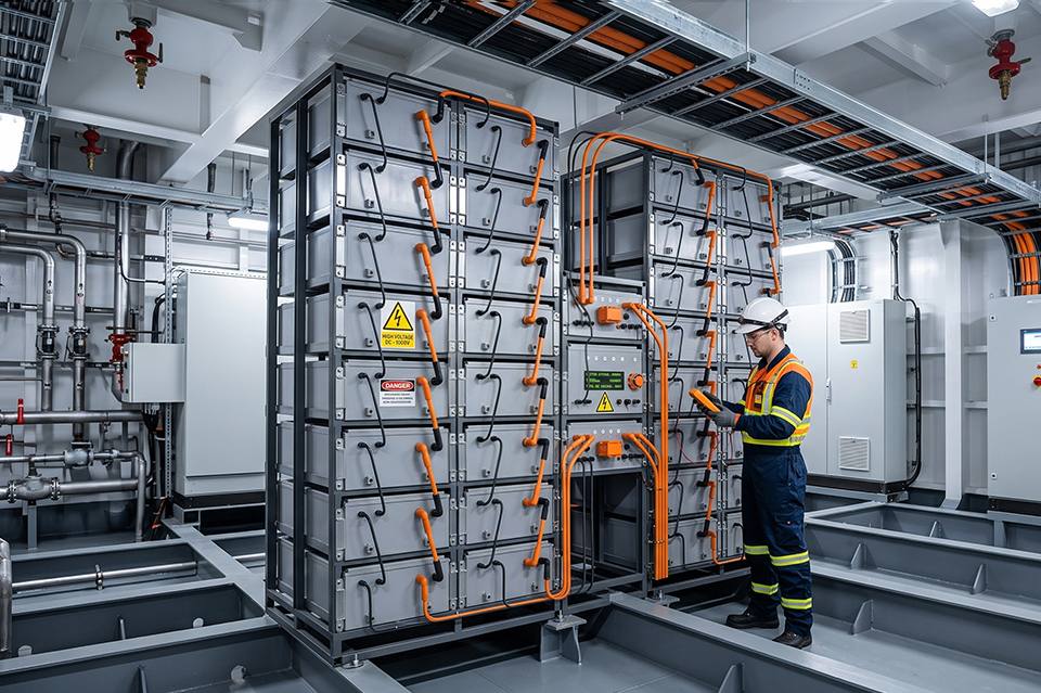
The battery space drives more of the general arrangement than most yards expect. Three requirements dominate: fire boundaries, gas venting, and access.
Location Constraints
Battery spaces carry restrictions that ripple outward through the arrangement:
- Fire boundary rating. The space typically requires A-60 or equivalent boundaries depending on adjacent compartments and flag requirements. That affects bulkhead construction and insulation volume.
- Separation from accommodation and control stations. Direct adjacency to manned spaces is usually restricted or requires additional mitigation.
- Separation from fuel and machinery. Proximity to fuel tanks, oil systems, and hot surfaces attracts additional class scrutiny.
- Escape route independence. The space needs an escape path that doesn’t require passing through the battery installation itself.
Ventilation and Gas Management
This is the requirement yards most frequently underestimate at arrangement stage.
Certified marine battery packs are fitted with explosion-proof relief valves designed to vent safely in a thermal event. On ROYPOW’s system, these are metal valves on the rear face of each pack, designed for direct connection to an exhaust duct.
That duct is a design object, not an afterthought. It needs:
- A defined route from every pack to a safe discharge point outside the vessel
- Sufficient cross-section for the full installed pack count, not a representative sample
- Clearance behind every rack for the connection itself
- Structural support along the run
- A discharge location away from air intakes, accommodation openings, and escape routes
Design that route at arrangement stage. Retrofitting a duct through a completed compartment is one of the most disruptive late-stage changes in a battery project.
Access and Maintenance Envelope
Modules are heavy, and they will be removed at some point in the vessel’s life.
- Plan a removal route wide enough for a module plus handling equipment
- Provide lifting points or padeyes above the racks
- Keep front-face clearance for connector access and inspection
- Confirm the route works with doors closed and the vessel afloat, not just during construction
Cooling Strategy Changes the Space
Cooling method determines how complex the compartment becomes.
|
Cooling Type |
Space Implications |
|
Liquid-cooled |
Pumps, coolant lines, heat exchanger, leak detection, drip trays, additional penetrations |
|
Air-cooled (forced) |
Fans, ducting, filters, redundancy for fan failure |
|
Naturally cooled |
Ambient temperature control only, no dedicated cooling subsystem |
Naturally cooled systems remove an entire mechanical subsystem from the compartment. Fewer penetrations, fewer failure modes, less maintenance access to plan, and a simpler class submission. ROYPOW’s high voltage marine battery system runs on natural cooling with IP67 protection throughout, which is worth weighing during compartment design.

Electrical Architecture and Integration Points
High voltage changes the electrical design far beyond the battery room. Anywhere the DC bus goes, new requirements follow.
The DC Bus Decision
System voltage sets almost everything downstream: conductor sizing, switchgear ratings, protection coordination, and insulation requirements.
Modern platforms give you a wide window. ROYPOW’s system covers 102.4V to 1000V through series module configuration, with single-system energy from 32.7 kWh up to 2,785 kWh, and parallel systems scaling to 100 MWh.
That range means the yard can standardise a module and vary the string configuration by vessel, rather than qualifying a different product for each hull.
Integration Points to Design Early
- BMS to power management system. Modern battery management systems no longer flood the vessel PMS with raw cell data. They present aggregated values and status. Confirm the communication protocol and data set with your electrical integrator during basic design, not commissioning.
- Inverter and drive compatibility. Verify the battery system is field-proven with your selected inverter platform. ROYPOW’s BMS has deployed with ABB and Danfoss inverters and COMAP and DEIF power management systems, which removes a meaningful category of integration risk.
- Emergency stop circuits. Class expects hard-wired emergency stop, both local and remote, independent of software. Route these as safety circuits from the start rather than adding them to an existing loom.
- Protection coordination. Certified systems fuse at both pack and PDU level. Your vessel-side protection has to coordinate with that, not duplicate or conflict with it.
- Shore power interface. Charging infrastructure, connector standard, and available shore capacity should be confirmed before the charging system is specified. A vessel designed for 1 MW charging at a berth offering 250 kW is a planning failure, not an engineering one.
Weight and Stability
Battery mass concentrates in one compartment, and it doesn’t burn off during the voyage. Unlike fuel, it’s a constant.
- Include full installed mass in the lightship estimate from concept
- Model the vertical centre of gravity of the battery space specifically
- Account for future capacity expansion in the stability margin if the design anticipates it
- Remember that removing fuel capacity in a hybrid conversion changes free surface effects as well as total mass
Ask your battery supplier for module mass and dimensions in writing at tender stage, before contract. Weight figures that arrive during detail design have a habit of being larger than the ones quoted verbally.
ROYPOW’s BMS fundamentals guide is a helpful reference when briefing electrical teams unfamiliar with lithium system architecture.
What the 2026 Class Rule Updates Changed
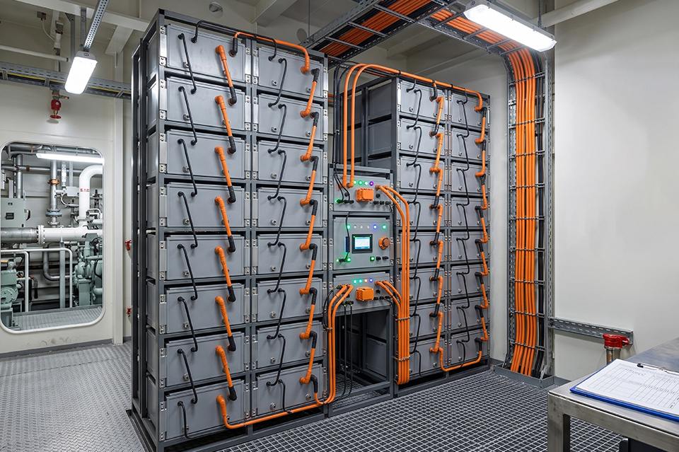
Class rules moved meaningfully in 2026, and several changes affect yard-side design directly.
DNV July 2026 Edition
The July 2026 edition of DNV’s rules for ships and offshore units introduced new class notations aimed squarely at the electrification transition. Two matter most to shipyards:
- Battery ready. A notation for vessels prepared to receive batteries as part of the main energy installation, without the batteries being installed at delivery.
- Shore power ready. The equivalent notation for vessels prepared for shore power connection.
These notations formalise something forward-looking yards were already doing informally. They give owners a defined, certifiable way to build a hull now and electrify later, which changes the commercial conversation on newbuilds significantly.
ISO Standards for Small Craft
For vessels up to 24 metres, two standards now apply concurrently:
|
Standard |
Scope |
|
ISO 23625 |
Lithium-ion battery system requirements |
|
ISO 16315:2026 |
Electric and hybrid propulsion system integration |
The division matters. ISO 23625 governs the battery itself. ISO 16315 governs how you integrate it. A compliant battery installed non-compliantly still fails.
ABS and Regional Requirements
The ABS Rules for Building and Classing Marine Vessels 2026 edition took effect 1 January 2026. For US-flag work, 46 CFR Part 111 Subpart 111.15 continues to govern battery construction and installation, classifying installations by charger output and requiring construction suited to marine temperature, vibration, and shock conditions.
Where Responsibility Actually Sits
This point deserves emphasis because it’s routinely misunderstood.
Component certification is the supplier’s responsibility. Installation compliance is the yard’s.
A DNV type approved battery system does not make an installation compliant. It removes the battery from the scope of what class must assess in detail, which accelerates approval considerably. The arrangement, segregation, ventilation, protection coordination, and documentation remain yard scope.
Choosing an already-certified platform is therefore a schedule decision as much as a technical one. ROYPOW’s marine systems hold DNV Type Approval alongside UN 38.3, and existing DNV test records can typically be reused to accelerate ABS certification rather than repeating the test programme.
Designing Hulls That Accept Tomorrow’s Battery
Battery energy density improves steadily. Charging infrastructure expands. Emissions regulations tighten. A vessel delivered today with a 500 kWh installation may want 1,200 kWh in 2032, and the difference between a straightforward upgrade and an uneconomic one is decided at design stage.
What Battery Ready Actually Requires
The DNV notation gives a framework. The engineering underneath it comes down to reserving the things that are expensive to add later:
- Volume. Reserve compartment space for the expanded configuration, even if it’s used for stores initially. Volume is cheap at design stage and close to impossible to create later.
- Structural capacity. Design deck and foundation scantlings for the future mass, not the delivered mass. Reinforcing structure inside a completed compartment is major surgery.
- Cable routing capacity. Oversize cable trays and penetrations. Pulling larger conductors through undersized penetrations means cutting structure.
- Switchgear space and rating. Leave physical room in the switchboard and select ratings with headroom.
- Ventilation and exhaust capacity. Size the venting arrangement for the maximum anticipated pack count, not the initial installation.
- Stability margin. Carry the future mass and vertical centre of gravity through the stability calculation as a documented case.
Why Modular Standardisation Compounds This
A modular platform makes future expansion a procurement exercise rather than a redesign.
If your installed system uses the same module as the expanded system, growth means adding modules to reserved racks. The BMS architecture, communication protocol, protection scheme, and class documentation all remain valid.
If your supplier changes module design between orders, none of that carries forward.
The Fleet-Level Benefit
For yards building series vessels or serving repeat operators, standardising on one module across the whole book of work delivers real advantages:
- One class submission template rather than one per hull
- One integration profile for electrical subcontractors
- One training programme for commissioning teams
- One spare parts specification for owner handover
- Predictable, repeatable installation labour hours
Retrofit as a Design Discipline
The same thinking applies in reverse for conversion work. An existing vessel with sound structure and a functional drivetrain is often a better electrification candidate than a newbuild, and the design questions are nearly identical: where does the battery go, how does it vent, how does it connect, and what does class need to see.
ROYPOW’s electric retrofit solutions are built around that pathway, and the platform is available in both MBmax16.3H and MBmax14.3H configurations to suit different energy and power profiles.
Pro tip: Document your battery-ready provisions formally, with reserved volumes, structural allowances, and cable capacities marked on the approved drawings. An undocumented provision is functionally identical to no provision, because the next engineering team won’t know it exists.
Build It Right the First Time With ROYPOW
High voltage integration rewards yards that treat the battery as a design input rather than a purchase order. Decide the operating profile early, reserve the space honestly, route the venting before the compartment closes, and choose a certified platform that shortens the class conversation instead of extending it.
Key takeaways from this guide:
- Battery specification belongs in concept phase, because it constrains general arrangement, structure, HVAC, and stability
- The operating profile and charging window determine system size more reliably than a headline kWh figure
- Exhaust ducting from pack relief valves is an arrangement-level design object, not a detail-design addition
- Naturally cooled systems remove pumps, coolant lines, and leak detection from the compartment entirely
- Component certification is the supplier’s scope. Installation compliance stays with the yard
- DNV’s July 2026 edition added Battery ready and Shore power ready notations for staged electrification
- ISO 23625 and ISO 16315:2026 apply concurrently on craft under 24 metres
- Reserve volume, structural capacity, cable routing, and ventilation for the battery you’ll want in 2032
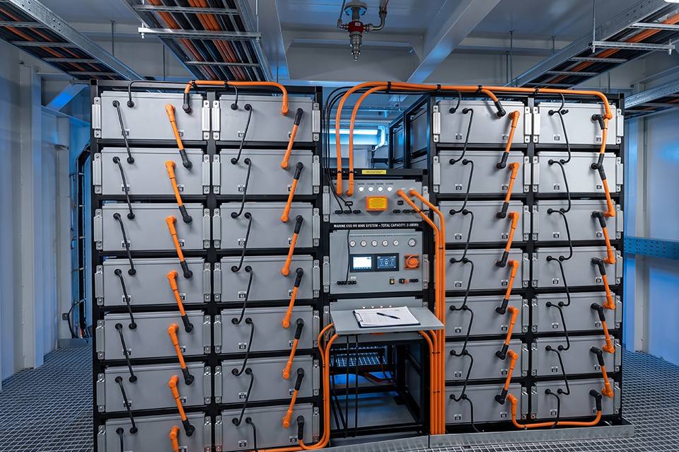
ROYPOW’s high voltage marine battery system is DNV type approved, naturally cooled, IP67 rated, and built on a single repeating module that scales from 32.7 kWh to 2,785 kWh across a 102.4V to 1000V range. For yards standardising across a series or planning a retrofit programme, their engineering team can work from your operating profile directly. Start at the contact page.
Frequently Asked Questions
When should a shipyard specify the battery system?
During concept design. Battery mass, volume, ventilation, and fire boundary requirements constrain general arrangement, structure, and stability before detail design begins.
Does a certified battery make the installation compliant?
No. Type approval covers the battery system only. Arrangement, segregation, ventilation, protection coordination, and documentation remain the shipyard’s responsibility.
What does the DNV Battery ready notation mean?
Introduced in DNV’s July 2026 edition, it certifies that a vessel is prepared to receive batteries as part of its main energy installation at a later date.
How much space should a battery compartment reserve?
Enough for the installed modules plus exhaust duct routing, front-face access, and a module removal path. Reserve additional volume if future capacity expansion is anticipated.
Which standards apply to lithium batteries on small craft?
ISO 23625 governs the battery system and ISO 16315:2026 governs propulsion integration. Both apply concurrently on vessels up to 24 metres.
Does natural cooling simplify shipyard integration?
Yes. It removes pumps, coolant piping, heat exchangers, and leak detection from the compartment, reducing penetrations, maintenance access requirements, and class submission complexity.